Grab a 1¼‑inch drive pipe, a couple of tees, a ball valve, a spring‑loaded waste valve, and a 4‑inch PVC pressure chamber with a bicycle‑tube air bladder. Cut the drive pipe at least 150 times its diameter, slope it about 20 %, and glue the tees and unions together. Install the waste valve opposite the outlet, add a swing‑check, and attach a 1‑inch delivery hose. Prime the system, set the ball valve for ~10 psi back‑pressure, and watch the water‑hammer lift about 0.33 gpm. Fine‑tune the spring and valve angles, bleed any trapped air, and you’ll have a reliable off‑grid pump—keep going to uncover the tweaks that keep it humming smoothly.
How a Hydraulic Ram Pump Works for Off‑Grid Water
If you’ve ever watched a stream rush past a hillside and wondered how you could lift that water up without a generator, the hydraulic ram pump is the answer. You’ll love how it squeezes energy out of water‑hammer dynamics, turning a fast‑moving stream into a pressure spike that pushes a portion of water uphill. The waste valve slams shut, the sudden stop creates that spike, and the delivery valve opens just long enough to fill your pressure chamber. Then the waste valve reopens, the cycle repeats, and you get a self‑sustaining lift. For off‑grid efficiency, you’re basically trading volume for height—most of the flow goes out the waste, but the water you keep gains the elevation you need without any electricity. The pump’s efficiency hinges on the conversion of velocity head into pressure head via the water‑hammer effect. Properly sizing the drive pipe length is critical for maximizing the water‑hammer surge that powers the pump. Understanding hydraulic pressure is essential for selecting the right components and preventing leaks. Using a high‑velocity airflow can also help clear debris from the intake, ensuring smoother operation.
Gather Materials and Tools for a DIY Hydraulic Ram Pump
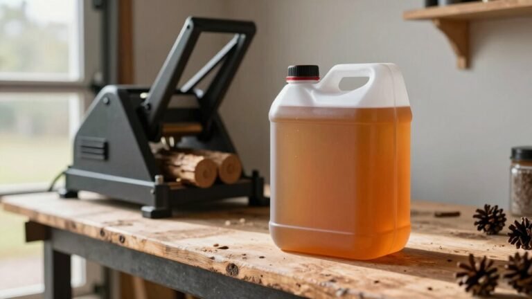
You’ve just seen how a fast‑moving stream can be turned into a pressure spike that lifts water uphill, so let’s get the parts together before you start building. First, make a material sourcing list: two 1 ¼‑inch tees, a 1 ¼‑inch ball valve, union, brass swing check, and spring check valve; a 3 ¾‑inch tee, valve, union, and the two bushings (1 ¼‑inch × 3 ¾‑inch and 3 ¾‑inch × ¼‑inch). Add the air chamber – a 4‑inch × 24‑inch PR160 pipe, glue cap, coupling or reducer, a bicycle inner tube, and a 6‑inch PVC nipple. Grab a ¼‑inch pipe cock, 100‑psi gauge, threaded cap, check valve with arrow, and garden‑hose adapter. Tools: Sharpie, ruler, hack or band saw, PVC primer and cement (≈$6), and Teflon tape. Do a quick cost estimation; most items are under $30 total, keeping the project budget‑friendly. The system requires a steady flow of water to generate sufficient pressure. Selecting the right hydraulic fluid is crucial for ensuring the pump’s seals and hoses remain protected and operate efficiently. Regularly checking fluid condition helps prevent contamination that could degrade performance. Using the proper viscosity grade of hydraulic fluid can extend the life of the pump’s components.
Cut and Assemble the Drive Pipe and Main Junctions
When you’ve got your drive pipe measured, marked, and ready to go, the next step is cutting it to the right length and snapping together the main junctions before the ram can even see a drop of water. Grab a pipe cutter or a hacksaw and slice the material pipe to the minimum 150‑times‑diameter length you calculated—usually a few dozen feet. Snap off any burrs, then dry‑fit the 1‑1/4″ valve to the 1‑1/4″ union, followed by the 3/4″ bushing and tee. The good news is you can glue the end assembly first, then thread the 3/4″ pipe into the tee for a solid seal. Secure the pipe with bolts or tie‑downs, keeping it straight and on a steady 20 % slope. What most people don’t realize is that a rigid, well‑aligned material pipe gives the water‑hammer shock the best chance to build, so take your time on these main junctions. The drive pipe must remain level and secured with rocks to prevent raised spots that could disrupt the pressure wave. Remember to bleed air from the system before initial testing to avoid cavitation.

Critical Sizing Note - Please Read Before Buying: This 1-1/4" PVC Union has an actual inner diameter of 1.660 inches (42.16mm). It is specifically designed to fit standard 1-1/4" PVC SCH40 pipes, which have an outer diameter (OD) of 1.660" (42.16mm). Please measure your pipe's OD to ensure it matches 1.660" before ordering. If your pipe's outer diameter measures only 1.25", this fitting will be too large

Pipe Connectors: It will be easier to connect two pipes for future repairs and replacement of pipes.

Great for high pressure applications: Use for any residential or commercial high-pressure water flow management needs; It is perfect for indoor plumbing, outdoor irrigation and sprinkler systems, and piping for an above ground pool, hot tub, or spa
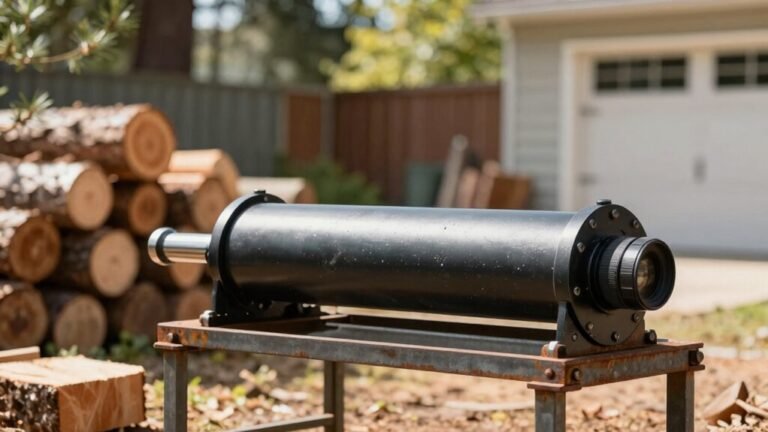
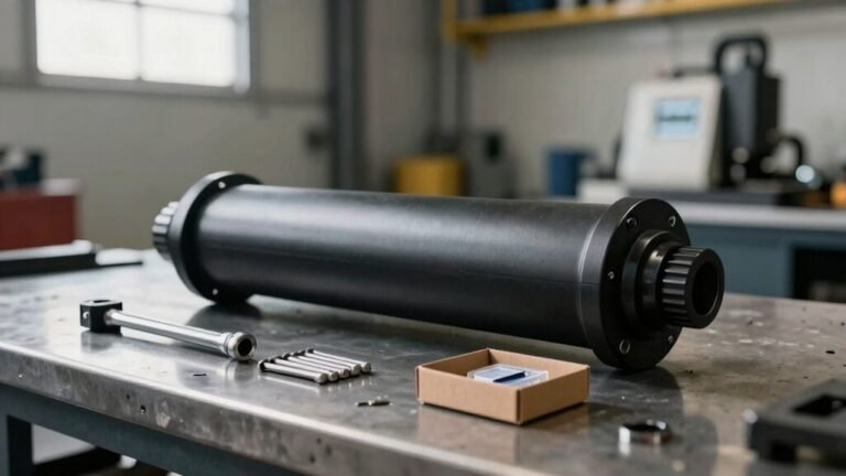
Construct the Pressure Chamber With an Air‑Spring Bladder
You’ll want the pressure chamber to act like a cushion for the water‑hammer shock, and the easiest way to do that is by stuffing a partially inflated bike inner tube into a sturdy PVC pipe. First, prime the pipe, cap, and adapter with PVC cement, then slide the squishy bladder in so the membrane material fills the interior without touching water. Keep the valve positioning outward—this lets you reach the Schrader stem easily for inflation or re‑charging. Once the tube sits snugly, cement the cap and adapter onto each end, clamp the assembly, and let the cement cure. The air bladder now separates air from water, cushions pressure spikes, and keeps the chamber from waterlogging, extending your pump’s life. The RP100 model uses a leather tank as an air chamber, providing flexible cushioning and durability. Properly sealing the connections prevents air leaks that could reduce efficiency. Higher CFM ratings in leaf blowers indicate greater airflow power, which parallels the importance of sufficient airflow in a hydraulic ram’s pressure chamber for efficient operation.

Safe For All Pipes: Operates effectively within 40-80 PSI water pressure range, ensuring controlled expansion to protect plumbing pipes during powerful unclogging action on shower drains, sinks, and main lines.

With accessories: It comes with manual inflatable ball, no need for additional inflatable equipment. When using the 6 inch or 8 inch inflatable plug, open the inflatable valve first to let the air fully enter the plug, then close the valve to start inflating, which will save more energy

With accessories: It comes with manual inflatable ball, no need for additional inflatable equipment. When using the 6 inch or 8 inch inflatable plug, open the inflatable valve first to let the air fully enter the plug, then close the valve to start inflating, which will save more energy
Build the Spring‑Loaded Waste Valve for Water‑Hammer Cycling
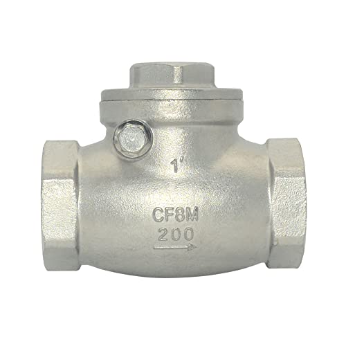
The pressure chamber you just sealed with the bike‑tube bladder needs a way to let water rush through, then slam shut at just the right moment— that’s where the spring‑loaded waste valve comes in. For material selection, grab a brass swing‑check valve; its weight keeps the flapper from closing too early, and a 1‑inch size gives you the punch you need. Stainless‑steel flappers work too, but avoid lightweight PVC. Now focus on valve geometry: mount the valve opposite the outlet with a 90‑degree elbow, and use a T‑piece for a side inlet that stabilizes flow. Install a spatula‑style spring behind the flapper, adjusting its position to fine‑tune tension. Screw in a stop so the valve never opens past the ideal angle, and you’ll get that crisp water‑hammer cycle every time. Bleeding the hydraulic system after installation removes trapped air and prevents pressure spikes. Gentle blotting can also help clear any residual fluid before final testing. Always store hydraulic fluid away from ignition sources, as its flammability risk can cause dangerous fires.

EASTMAN BRASS SWING CHECK VALVE: The Eastman swing check valve features a mechanism specifically engineered as a backflow preventer, protecting your water systems from contamination and damage

Size - 1" Female Thread Swing Check Valve. Note,This thread is not an NPT thread, please refer to the dimensional drawing for specific diameters.

ONE WAY FLOW CONTROL -- It is a kind of valve that relies on the pressure of the medium to produce the effect of preventing the backflow of the medium. Only allows the medium to flow in one direction, to prevent the medium backflow.
Install the Check Valve and Connect the Delivery Hose
A solid check valve is the heart of your ram’s delivery side, and getting it right means the pump will actually push water out instead of just sloshing inside. First, turn off the water and clean the pipe ends. Thread the stainless‑steel swing check valve onto the cemented bushing, making sure the arrow points down toward the main tee—this is the proper valve orientation. The stem should drop straight down so the flapper faces downwards when the pump sits upright. Next, attach the delivery hose. Choose a hose size that matches the 1‑inch valve outlet; a too‑small hose will choke flow, while an oversized one wastes pressure. Slip the hose onto the outlet, tighten the compression ring, then give it a firm tug to confirm a tight seal. Finally, prime the system, bleed any air, and you’re ready to watch water surge out. Adding a stand pipe can shorten the cycle time, but it does not increase the overall water volume delivered. Selecting the right pump type ensures the system can handle the required pressure and flow for heavy‑duty timber operations. Wear appropriate protective gloves to prevent skin contact with contaminated hydraulic fluid. Always check hydraulic fluid before starting the pump to avoid damage from low or contaminated fluid.
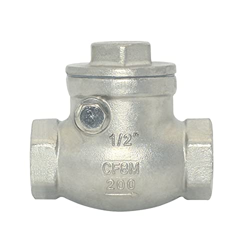
Body Material:Stainless Steel 316,200PSI/PN16,ANSI B1.20.1,Includes stainless steel 316 disc and screwed cap
Body Material:Stainless Steel 316,200PSI/PN16,ANSI B1.20.1,Includes stainless steel 316 disc and screwed cap

ONE WAY FLOW CONTROL -- It is a kind of valve that relies on the pressure of the medium to produce the effect of preventing the backflow of the medium. Only allows the medium to flow in one direction, to prevent the medium backflow.
Mount, Prime, and Secure the Pump
After you’ve got the check valve and delivery hose snug, the next step is to get the whole pump set up where it can work without wobbling or flooding. First, choose a low spot near the water source, but keep it off the streambed to avoid debris and flood damage. Anchor the pump for mount stability using bolts, galvanized tie‑downs, or a concrete pad; a wooden block or decking board works fine if you tape and strap it securely. Tilt the stainless valve slightly off‑center for easier operation. Now comes pressure priming: close the delivery valve, submerge the inlet, and fill the pressure chamber through the Schrader valve or by running a short flow. Tighten all couplings hand‑tight then wrench, and double‑check O‑rings before you finish. This solid, primed setup keeps the pump upright and ready for the next phase. The short drive pipe of about 22 ft helps the pump cycle faster while still providing adequate flow. Echo’s design also emphasizes lighter weight for easier handling in residential settings. Remember to wear protective eyewear when testing the blower to prevent eye injury. Some municipalities have enacted noise ordinances that restrict the operation of gas‑powered equipment in residential areas.
Fine‑Tune Valve Settings for 10 psi Back‑Pressure and 0.33 gpm Flow
Getting 10 psi of back‑pressure while keeping the flow steady at about 0.33 gpm is mostly about fine‑tuning the delivery valve and watching the pressure gauge work its magic. First, close the ball valve just enough to create artificial back‑pressure; you’ll feel the pressure sealing tighten as the gauge climbs toward 10 psi. Next, watch the valve timing: each cycle should build pressure, then the waste valve snaps shut, sending a spike through the spring check. If the pump stalls, back the valve a tad more and re‑check the gauge. Use a 45‑degree cut on the delivery valve to restrict flow without choking the pump. Finally, verify the flow by timing a one‑gallon bucket; you should hit roughly 0.33 gpm while the gauge stays steady at 10 psi. Debris can block the intake and reduce water flow, so ensure the inlet is clear before adjusting the valve. Proper log splitter maintenance can prevent debris buildup and keep the system running smoothly. Avoid inhaling hydraulic fluid vapors, as they can cause respiratory irritation.
Troubleshoot and Maintain Your Pump
When your hydraulic ram starts coughing, sputtering, or just won’t cycle, the first thing to remember is that most problems boil down to three basics: water flow, air cushion, and mechanical wear. Check the intake screen; a tiny opening starves the pump. Make sure the drive pipe isn’t too long or the wrong diameter, and verify the creek’s flow is steady—bubbles will ruin the air cushion. Inspect the pressure vessel: you need a pocket of air, not a full water column, and the water level should stay below halfway. Listen for high‑pitched whining; that’s cavitation from air collapse. Finally, watch valve timing—if the check valve sticks or the pilot valve closes too early, the cycle stalls. Tighten loose fittings, clear filters, and you’ll have the ram humming again. Make sure the input head is at least 2.5 ft to provide sufficient pressure for valve cycling.