You turn the engine’s rotating shaft into crushing power by letting it drive a pair of meshing gears that trap a fixed volume of oil, pull it in, and compress it into high‑pressure flow. A low‑pressure gear gives you the big‑volume stream for fast cutting, while a smaller high‑pressure gear kicks in at 700‑800 PSI for that split‑force push. An unloading valve vents excess pressure back to the tank, keeping the pump cool and the engine light‑loaded. Pascal’s Law then multiplies the tiny force from the piston into the massive thrust you feel on the log. The oil travels from the vented reservoir through a filter, into the pump, out to the cylinder, and back—forming a closed loop that you size by matching piston area to desired PSI and flow to stroke speed. Keep the fluid clean, watch the filter, and you’ll avoid the most common hiccups. Stick around and you’ll see how each component ties together for smoother cuts and splits.
How a Pump Turns Engine Power Into Hydraulic Pressure
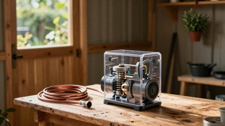
When you fire up the engine on your wood‑chipper or log splitter, the real magic starts the moment that rotating shaft meets the pump gears. The shaft’s torque drives a set of meshing gears that trap a fixed volume of fluid each turn, turning mechanical power into hydraulic pressure. As the gears separate at the inlet, they create a vacuum that pulls fluid from the reservoir, then push it toward the outlet where the teeth compress it, raising pressure. This positive‑displacement action gives you high pump efficiency and smooth delivery. Because the fluid moves in sealed pockets, you also get noticeable noise reduction compared with open‑flow designs. The result is a powerful, quiet system that lets you chip wood or split logs with consistent force. Selecting the right pump type—gear, vane, piston, or axial‑flow—ensures optimal performance for the specific demands of timber processing equipment, such as high pressure and durability. Using a fluid with the proper viscosity, such as 32–46 cSt for light‑duty units, helps maintain pump efficiency and protects against wear. Properly sizing the pump to match the system’s flow rate maximizes energy efficiency and prevents overheating.
Why Most Log Splitters Use a Two‑Stage Gear Pump
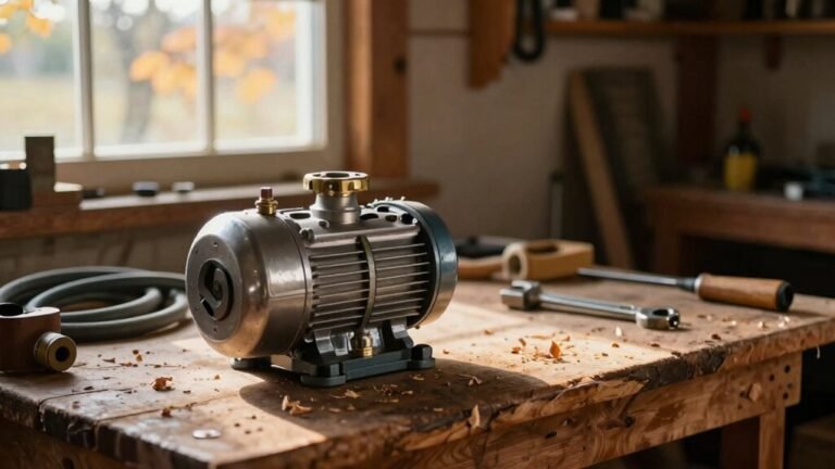
The pump you just watched turning engine torque into hydraulic pressure is only half the story; the real secret behind a fast, powerful log splitter is the two‑stage gear pump tucked inside the hydraulic box. You’ll notice it has a big gear set and a small one, each spinning at the same speed but sized for different jobs. At low pressure both gears feed oil, giving you high flow for quick cylinder travel. When you hit a heavy load, the bypass valve shuts the large gear, letting the small gear generate the high pressure you need to crush that log. This design boosts pump reliability because each stage handles what it’s built for, and it slashes cost efficiency by using a single, compact unit instead of two separate pumps. The result? Faster splits, less engine strain, and a more affordable splitter that still feels rugged and dependable. The unloading valve senses pressure and redirects flow to keep engine load low at high pressure. Proper hydraulic fluid storage prevents fire hazards and ensures consistent performance. Selecting the right viscosity grade helps maintain optimal flow across temperature variations. Always check for air before starting the cycle to avoid pressure spikes.
Low‑Pressure Gear: Generating High Flow for Fast Cutting
Ever wondered why your wood chipper seems to zip through branches at low pressure but stalls when the load spikes? The low‑pressure gear in a two‑stage pump is built for exactly that—high flow, fast cylinder speed. A robust gear pump design uses cast‑iron gears that split inlet fluid and whisk it around teeth to the outlet, delivering up to 28 GPM in low‑pressure mode. Because displacement is fixed, the flow stays steady even as pressure climbs, so your cylinder rushes forward quickly, keeping cuts clean and swift. The AP‑HL or APQ‑20‑25 models hit 11.84 GPM at 1800 RPM, and the 1.37 CID low stage pairs with a 0.51 CID high stage for seamless volume boost. The good news is you get rapid advance without sacrificing durability. A pressure gauge can confirm the system’s pressure range during operation. A hydraulic ram pump can convert water flow into the pulsating surge needed to drive the chipper’s piston. Properly seal inspection prevents leaks and extends cylinder life.

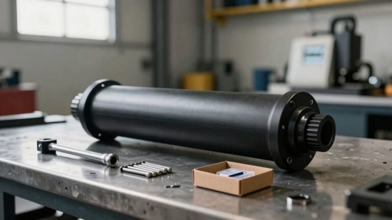
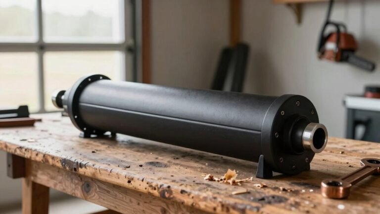
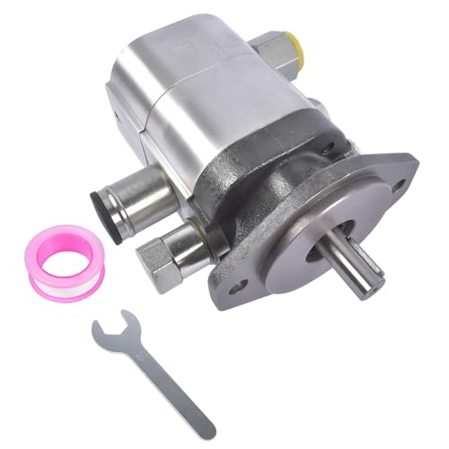
High Pressure Hydraulic Pump or Motor, Bi-directional rotation. Universal SAE A mounting flange and shaft sizes fit readily available pump/motor bell housing adapters and couplings. Many motors of this type are in appllications that this could be used to replace.

High-strength aluminum alloy casing, light weight, alloy steel hard-face gear transmission, stable transmission

【Original Part Number, Perfect Compatibility】Original part number: HGP-33A-F6-6R – A 1:1 precise match to your loader's hydraulic pump, requiring no modifications. We've optimized the displacement, pressure, and control methods to perfectly match the engine power, weight, and performance requirements of all standard loaders, solving the common problem of "parts mismatch leading to installation delays and equipment damage.
When the Log Splitter Pump’s High‑Pressure Gear Engages (700‑800 PSI)
Because the pump’s load‑sensing pin hits that 700‑psi sweet spot, the high‑pressure gear kicks in and the whole system shifts from a high‑flow, low‑force mode to a muscle‑building, low‑flow mode. You’ll feel the pressure‑threshold hit around 700‑800 PSI, and the small displacement gears—0.13‑0.194 cu in./rev—start delivering a focused 4 GPM stream. The valve timing tightens, keeping the unloading valve from opening until pressure climbs above the set point. That’s the thing: the high‑pressure gear’s thrust plates and seals take the load, so you must watch seal wear. Regular oil checks and proper filtration keep the seals happy, preventing premature wear and ensuring your splitter stays strong. Using the correct hydraulic fluid is crucial for maintaining pressure stability and protecting component longevity. Selecting the right fluid also depends on its viscosity index to ensure consistent performance across temperature variations. Monitoring fluid discoloration can alert you early to contamination issues.
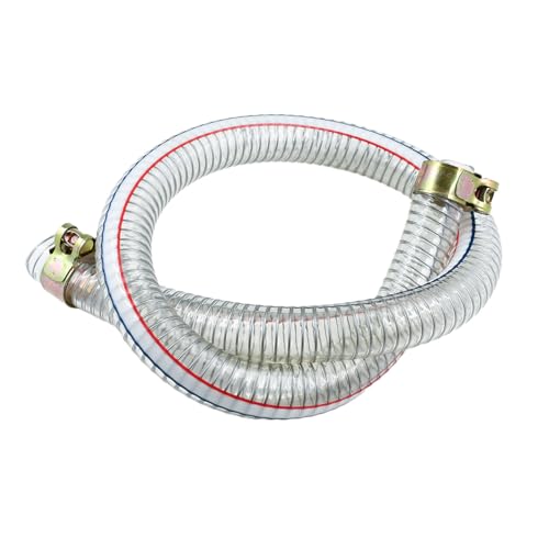
Versatile Use Cases – Universal steel wire–reinforced PVC suction hose designed for low-pressure hydraulic inlet and return line applications (max working pressure: 30 PSI; burst pressure: 60 PSI). Suitable for log splitter pump inlets and fluid tank connections.

【Spec】First Stage: 28 GPM; Second Stage: 7.6 GPM;Pressure: 4000 PSI intermittent, 3000 PSI continuous;Max RPM: 4000

Industrial-Grade Durability – Reinforced with high-tensile steel wire and thick PVC, this 39'' length 1" id universal log splitter hose resists kinks, abrasion, and hydraulic oil degradation, ensuring longevity for log splitter parts systems
How the Unloading Valve Keeps Flow and Pressure in Check
When the pressure in your splitter’s circuit climbs past the set point, the unloading valve swings open and instantly redirects the pump’s flow to the tank, keeping both flow and pressure in check. The valve’s spring‑loaded poppet or spool reacts to that pressure spike, and once hydraulic force overcomes the spring tension, it dumps the excess flow. The good news is that during this unload phase the pump runs at low pressure, slashing energy use by up to 90 % and keeping heat down. Energy valve design focuses on that spring‑pilot balance, so when pressure drops back below the set point the spring snaps the valve shut, restoring full flow to the cylinder. This simple pressure regulation protects your pump, saves electricity, and lets you switch smoothly between high‑speed approach and high‑pressure work without a separate relief valve. High‑low pump systems typically employ an unloading valve to redirect flow when pressure reaches a preset level, ensuring efficient operation. Using the corrosion‑resistant hydraulic fluid can further safeguard metal components from wear.
Pascal’s Law: How a Log Splitter Pump Amplifies Small Input Force
The unloading valve keeps your splitter from over‑pressurizing, and once that pressure is capped, the real magic happens inside the pump itself: Pascal’s Law lets a tiny push on a small piston become the massive force that drives a log‑splitting cylinder. When you press the pump handle, you create pressure in a tiny chamber. That pressure spreads instantly, undiminished, to the larger cylinder piston. Because pressure stays constant, the larger area experiences pressure multiplication, turning your modest input force into a huge output. This is hydraulic leverage in action—your 10 lb push on a 1 in² piston can produce 100 lb on a 10 in² cylinder. The result? You split logs with barely any effort, thanks to the physics that lets a small force become a big one. The fluid particles distribute force evenly throughout the system, ensuring the pressure remains uniform across all surfaces. Properly sized directional control valves guide the flow to the appropriate cylinder, enhancing both safety and efficiency. Before starting, always purge air from the hydraulic lines to prevent spongy operation and maintain consistent pressure. The system’s pressure flow relationship determines how quickly the cutter or splitter can operate under load.
Oil Path in a Log Splitter Pump: From Reservoir to Cylinder
Even if you’ve never opened a hydraulic system before, the oil’s journey from the tank to the cylinder is pretty straightforward once you picture the loop. You start at the reservoir, where the vented cap lets air escape while a simple filter keeps dirt out. The suction line, positioned a few inches above the bottom, draws clean oil past any reservoir sludge that might settle. From there the oil slides into the pump inlet at near‑zero pressure, gets pressurized, and heads to the directional valve. When you pull the handle forward, the valve shunts the flow to the cylinder’s base port, pushing the piston out. After work, the oil returns via the rod‑end port, travels the low return line, and drops back into the tank, completing the closed loop. Verify ram position to avoid spillage during filter change. If you notice persistent air bubbles, consider performing a bleed procedure using a clear hose to purge trapped air. Always check fluid level before each use to ensure proper hydraulic performance. Regularly inspect the fluid for contamination signs to catch wear early.
Pick Cylinder Size and Pump Flow for Desired Tonnage
If you’ve got a specific tonnage in mind for your log splitter or press, the first step is picking a cylinder that can actually deliver that force, and then matching a pump that can move enough oil fast enough to make the machine work at the speed you want. For cylinder sizing, start with the desired force and use the PSI‑×‑area formula; a 5‑sq‑in piston at 3000 PSI gives roughly 15,000 lb (7.5 tons). Next, calculate the minimum PSI, double it for safety, and then select a pump rated about 20 % higher. Pump flow ties directly to speed: 4 GPM or more for rapid splits, 1‑2 GPM for slower, precise presses. Remember, a larger bore needs more flow to keep the stroke time reasonable, so balance bore size with a pump that can deliver the required GPM without overheating. Selecting the right hydraulic fluid, viscosity range is crucial to maintain consistent performance across temperature variations.
🔧【Unmatched Performance】- Weonefit 2-stage HI/LO gear pump. Experience exceptional efficiency with our hydraulic wood log splitter pump, featuring a maximum speed of 3600 RPM, a maximum operating pressure of 3000 PSI, and a high flow rate of 22 GPM. Tackle any wood processing task with ease and power. The 2-stage pump can provide faster cycle times and higher possible pressure.

Exceptional Performance at Your Fingertips: With a remarkable maximum speed of 3600 RPM, a maximum operating pressure of 4000 PSI, and a 22 GPM high flow rate, our hydraulic wood log splitter pump is your ultimate solution for tackling all types of wood. This hydraulic gear pump excels in both speed and force, ensuring efficient wood splitting like never before, making it your go-to tool for any wood processing task.

Universal Compatibility: Fits models 221006,cp75210,CP-752-10,723-0405,120-818 and log splitters/mini excavators
Common Maintenance Mistakes and How to Avoid Them
When you skip the little things like checking fluid levels or swapping out a clogged filter, you’re basically inviting trouble before it even starts. Ignoring fluid checks lets low oil cause cavitation, overheating, and pressure loss. The good news is a quick visual check each week catches most issues. Filter contamination is a silent killer; if you let a dirty filter sit, you’ll see filter clogging, reduced flow, and hard starting. What most people don’t realize is that a bi‑annual fluid analysis and a 5‑micron breather cap keep particles out of the system. Also, flush cooler lines quarterly and use dry‑break couplings when you change attachments. Regular lubrication of bearings, pivots, and chains with 10W/30 oil or grease prevents binding and costly repairs. Contaminated fluid is the primary cause of most pump failures.

Universal Formulation: This military-grade “one-fluid” is suitable for tractor hydraulic systems, wet brakes, transmissions, and diesel engines, making it an excellent fluid for agricultural machines
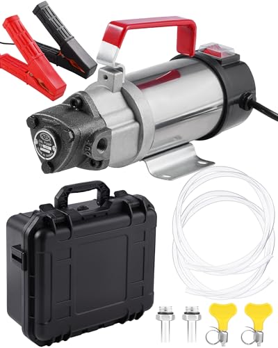
Built for Thick Oils: Upgraded pure copper motor deliver strong, stable suction for thicker fluids like SAE 5W-30, 10W-30, 20W-50 engine oil, common gear oils up to SAE 75W-90, transmission fluid and diesel fuel.

IMPORTANT: MUST ROTATE SHAFT CLOCKWISE WHEN LOOKING AT THE SHAFT. IMPROPER ROTATION DIRECTION COULD LEAD TO SHAFT LEAKAGE AND SEAL FAILURE.