First, make sure the reservoir is full and the pump is off, then attach a clear hose to the cylinder’s bleed port and position the cylinder below the pump with the port facing up so air can rise. Open the vent, slowly extend and retract the ram a few times, and watch for foam‑free fluid flowing out; tighten the bleed valve once only clear oil comes out. Do the same on the opposite side for a double‑acting cylinder, keep the fluid level above the halfway mark, and after a short test run you’ll notice the jerky motion is gone—if you keep going, you’ll uncover more tips for keeping your chipper or splitter running smooth.
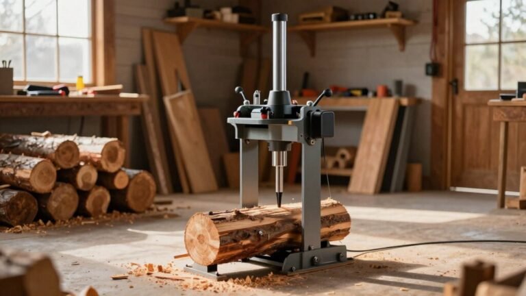
Why Air Makes Chippers and Log Splitters Jumpy
When air sneaks into the hydraulic circuit, your chipper or log splitter starts acting like a jittery kid on a trampoline. The trapped air bubbles act like a tiny air‑bag damping system, soaking up pressure then releasing it suddenly, so you feel that jumpy, uneven motion. Loose fittings or worn seals let air slip in, and a cracked pump shaft seal can suck it right into the oil. That air reduces the effective hydraulic pressure, making the cylinder hesitate and then lunge forward. You’ll notice slow pressure‑plate movement and a loss of force, especially on downhill‑facing machines or cold days when oil thickens. Proper valve‑spring tuning can help keep the flow steady, but the real fix is eliminating the air in the first place. Adjusting the pump set screw can increase pressure threshold to keep the pump in stage 1 longer, reducing the likelihood of air‑induced jerks. Using a clear hose at a high point of the system can help you see air bubbles as they escape during the bleeding process. Maintaining the fluid’s incompressibility ensures consistent power transmission and prevents performance loss.
Identify Air‑Related Symptoms Before Hydraulic Cylinder Bleeding
If you’ve ever felt your log splitter or wood chipper lag, jerk, or make a whining whine right before it fires, that’s a dead‑giveaway that air has snuck into the hydraulic circuit. You’ll notice a spongy feel when you pull the lever—air compresses, so the actuator response slows and the plunger moves in a jerky, pulsating fashion. Look for foamy fluid or bubbles in the reservoir; that’s a visual cue that fluid viscosity has dropped. A sudden temperature rise in the pump or cylinder often signals extra friction from trapped air. Finally, a quick vibration analysis will reveal abnormal chatter or increased vibration, confirming that system pressure is off and the system is working harder than it should. The reservoir must be filled near the fill line before bleeding. Regular fluid testing can detect moisture contamination before it degrades performance. Maintaining the correct fluid level also helps prevent cavitation damage in the pump. Ensure the machine is placed on a stable, level surface to avoid unintended movement during operation.
Gather Tools for Hydraulic Cylinder Bleeding
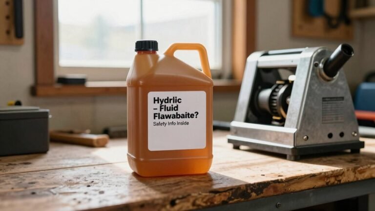
Gathering the right tools before you start bleeding a hydraulic cylinder is half the battle won. First, check your tool inventory: a complete wrench set, adjustable and box‑end wrenches, and a socket set with extensions will let you tackle any bleed valve without stripping threads. Add a torque wrench to keep fasteners snug after you finish. Next, grab safety gear—glasses, gloves, steel‑toed boots, and an apron—to keep splashes and pressurized fluid away from skin and eyes. A clear bucket or catch pan will show air bubbles as they escape, while absorbent pads under the container prevent spills. Finally, have a length of clear tubing and hose clamps ready to route fluid safely to your collection vessel. Ensure the cylinder is positioned below the pump level with ports facing upward to force air toward the pump for easier removal. Use absorbent pads to quickly contain any accidental drips during the process. Be aware that hydraulic fluid fire risk increases if fluid leaks onto hot surfaces or sparks. Always consult the equipment’s manual for the recommended hydraulic fluid type before beginning the bleed procedure.

Complete Master Cylinder Bleeder Kit: this master cylinder bleeding kit is a replacement for 14151; It includes 2 clear hoses, 10 pairs of red threaded fittings, 10 pairs of blue threaded fittings, 2 pairs of tees, a pair of clips, and a PTFE tape

Transparent Funnel: Liquid and bubbles are clearly visible during the bleeding of bicycle brakes.
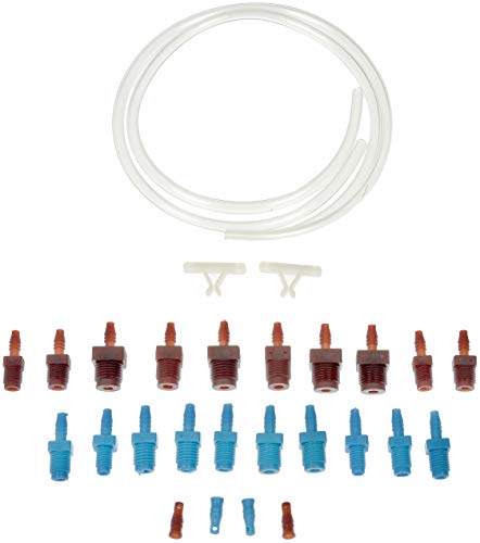
Complete kit - this master cylinder bleeding kit includes two clear PVC hoses, five pairs of threaded fittings, and a pair of tees
Set Up Hoses & Reservoir, Then Bleed a Single‑Acting Cylinder
You’ve already got your wrenches, safety gear, and a bucket ready, so the next step is getting the hose and reservoir set up before you start bleeding the cylinder. First, attach a clean hose to the single‑acting cylinder port, making sure the connection is tight to avoid leaks. Position the cylinder below pump level, port facing up, and elevate the pump so gravity helps push air upward. Open the reservoir vent or oil filler plug for reserv safety, then fill it with fresh hydraulic fluid of the proper fluid viscosity. Once the reservoir is full, extend the cylinder fully and hold it a few minutes; this lets any trapped air rise to the top. Open the bleed valve, let fluid flow free of foam, and tighten the valve when only clear fluid escapes. Repeat the extend‑retract cycle a couple of times to chase remaining air back into the reservoir, then verify smooth operation before moving on. Wear protective gloves while handling hydraulic fluid to prevent skin contact and contamination. Always dispose of used hydraulic fluid in a sealed, labeled container to comply with environmental regulations. Proper pressure monitoring ensures the system operates within safe limits and prevents premature wear.

【Universal Compatibility】Compatible with Seastar, Compatible with BayStar hydraulic steering cylinder, including inboard, outboard, and Sterndrive Hydraulic Helms. Ensures smooth refilling and bleeding of steering fluid.

One-way Flow: We have specially prepared one-way check valve in car one man brake bleeder kit, which plays a vital role in the whole working process, brake fluid/air can only flow out in one way, avoiding problems such as backflow of the old brake fluid/air

Features:fittings will not cross-thread, ensuring that the hydraulic steering kit will not leak or get dirty when bleeding.The fill tube is used for all outboard, sterndrive, and inboard hydraulic helms, makes it a breeze in filling the steering system
Set Up Hoses & Reservoir, Then Bleed a Double‑Acting Cylinder
Before you start bleeding a double‑acting cylinder, get the hoses and reservoir sorted out so the fluid can flow freely and the air has a clear path out. Turn off the machine, vent the system, and make sure the pump reservoir stays vented for hydraulic safety. Attach a clear hose to each coupler, fill it with oil, and secure the connections—this prevents leaks while you cycle. Position the cylinder so its ports point upward, then lower it below pump level to let gravity help air rise toward the reservoir. Begin slow advance‑retract cycles, watching the return hose for bubbles. When the motion feels smooth, close the bleeder valve and perform a quick pressure calibration to confirm the system is back in spec. The hydraulic ram pump creates a pulsating surge that can be harnessed to power auxiliary equipment like a wood chipper. Always wear protective gloves to prevent skin contact with hydraulic fluid. Understanding pressure dynamics helps ensure the cylinder delivers the required force without overloading the system.

🛥️ INCLUSIONS & APPLICATION: The Marine Tech bleed tube is used for all outboard, sterndrive, and inboard Seastar hydraulic helms. It makes the bleeding and filling process easier and simpler. The clear hose aids in seeing the air bubbles so you know you're doing it right from side to side. This hose makes getting the air out of a Seastar steering system super easy. If you are a professional or a do it yourself mechanic, this is a must have.

Saves time - the components included in this brake master cylinder bleeding tool kit are designed to make it possible to bench-bleed air from the brake system master cylinder on specified vehicles

Bleed the Entire Hydraulic System (From Farthest Fitting to Power Supply)
After you’ve got the hoses and reservoir sorted and the double‑acting cylinder is bleeding clean, it’s time to push the air out of the whole system, starting at the farthest fitting and working your way back to the power supply. Warm the engine, let it idle, and watch the fluid level stay above the halfway mark. Then pull the ram through eight to ten full extension‑retraction cycles; each stroke forces fluid—and any trapped bubbles—toward the reservoir. Keep an eye on the pressure‑balance gauge; it should stay steady as you move inward. If the ram feels smooth and the fluid flows without sputtering, you’ve cleared the air. Finally, tighten the oil filler plug securely to preserve the system’s integrity. Ensure RAM is fully extended before beginning the bleed cycle. Check the seal condition regularly to avoid premature wear. Also, verify that the pressure gauge reads within the manufacturer’s specified range during the bleed process. Hydraulic fluid temperature can rise significantly during heavy operation, so monitoring it helps prevent overheating.
Monitor Hydraulic Fluid Quality After Bleeding
If you’ve just finished bleeding the system, the next step is to keep an eye on the fluid’s health, because clean oil is the lifeblood of any wood‑chipper or log splitter. Start by checking fluid color; a clear‑to‑amber hue means you’re good, while milky or dark shades signal water or contaminants. Take a fresh sample while the machine runs and compare it to a new‑oil vial—shake both and note any differences. Then, track viscosity trends: a sudden drop often points to air entrainment or additive loss, while a thickening can mean oxidation or water buildup. Sample monthly or every 1,000 hours, log the results, and keep a baseline. If you see any shift, act fast before the pump or valve starts coughing. Recognizing a sweet petroleum scent can help you detect early fluid degradation. Understanding the corrosive potential of hydraulic fluid helps prevent metal wear and wood component damage. Proper fluid selection, such as using a high‑pressure hydraulic fluid formulated for heat resistance, is essential for maintaining system performance.
Common Bleeding Mistakes That Re‑Introduce Air (and How to Prevent Them)
Keeping an eye on fluid quality is only half the battle—once the oil looks good, you’ve got to make sure you don’t accidentally let air back into the system while you’re bleeding it. The most common slip‑up is over‑tightening the bleed valve; a little extra valve torque can strip threads, creating a tiny leak that sucks in air. Use a torque wrench and stay within the manufacturer’s spec. Next, watch your cylinder orientation. If the cylinder sits above the pump or is tilted wrong, air pools in the ports and refuses to rise toward the pump. Position the cylinder lower than the pump or tilt it so ports face upward, then run a few full cycles. Finally, avoid extending the rod under no load—free travel compresses trapped air and hurls it back into the line. Stick to controlled, loaded cycles and you’ll keep the system air‑free.
Troubleshoot Persistent Jerky Motions After Bleeding?
Even after you’ve bled the system and the fluid looks **crystal‑clear, those jerky motions can still pop up, and they’re usually a sign that something’s still off inside the cylinder or the line. First, check the rod seal for scratches, dents, or wear; a damaged seal lets fluid leak and creates uneven pressure spikes. Next, inspect the fluid for contamination—any particles or milky appearance can abrade the seal and cause the cylinder to “hunt.” If the seal looks good but the motion stays erratic, run the cylinder slowly through its full range a few times to chase out trapped air. Finally, verify that the valve settings** aren’t too tight, because a mis‑adjusted flow control can amplify any remaining seal or fluid issues.

【Universal Compatibility】 4 Size Hydraulic Seal Installers with Surface Mountable Twistor Handle Block and 2-Angles Seal Pick Multitool is a quick, safe and complete installation tool for flexible rod seals. 4 sizes to cover most rod seal installation job from 0.7" up (Rod Diameters): (XS) 20-30mm (0.7”-1.187” Rod) gland hole; (S) 30-50mm (1.187"-2" Rod) gland hole; (M) 50-70mm (2-2.75" Rod) gland hole; (L) 70-165mm (2.75"-6.5" Rod) gland hole.

VEHIFOMO Hydraulic Seal Installer: Rod seal install tool set is a quick and safe installation tool for flexible rod seals. Includes 3 sizes to cover just about any rod seal installation job from 0.87" up
Application:Hydraulic Cylinder Seal Kit fit for Case Crawler Tractor-Loader: 350 Crawler Tractor-Loader w/BH Models 26, 26B, 26C, 26S (Loader Grapple, Loader Hydra-Leveling, Loader Tilt); 580B Loader/Backhoe w/BH Model 35 (Loader Tilt, Logging Fork Grapple) ;580C Construction King Loader/Backhoe (Loader Bucket Tilt LH, Loader Bucket Tilt RH, Loader Grapple);
Maintenance Checklist to Keep Your Chipper or Splitter Air‑Free
Jerky motions after bleeding often point to hidden air pockets or a worn seal, but once you’ve cleared those, keeping the system air‑free is all about regular, disciplined maintenance. Follow an Air‑free maintenance routine each day: check oil levels, look for leaks, and glance at the pressure gauge for odd noises. Inspect hoses, connections, and cylinder seals for cracks or moisture, tightening or replacing as needed. Every week, run a Cylinder‑bleed checklist—filter fresh oil, wipe down breathers, and clean strainers. Monthly, change oil and filters per the manufacturer, and scrub all pipe and tank surfaces to keep dust out. Quarterly, examine the cylinder for wear, test smooth movement, and lubricate seals. Stick to this schedule and you’ll keep your chipper or splitter running smooth and air‑free.

【Universal Compatibility】 Hydraulic Seal Installer is a quick and safe installation tool for flexible rod seals. 3 sizes to cover most rod seal installation job from 0.87" up (Rod Diameters): (S) 22-40mm (0.87"-1.57" Rod) gland hole ; (M) 40-70mm (1.57-2.75" Rod) gland hole; (L) 70-165mm (2.75"-6.49" Rod) gland hole.

Multiple Size:#4 (1/4" Flat Face), #6 (3/8" Flat Face), #8 (1/2" Flat Face), #10 (5/8" Flat Face), #12 (3/4" Flat Face), #16 (1" Flat Face), #20 (1-1/4" Flat Face), #24 (1-1/2" Flat Face), #32 (2" Flat Face) O rings.

Application -Seal Kit Compatible with HC5340, HC5341, HC5342, HC5343, HC5344, HC5345, HC5346, HC5347, HC5348, HC5358, HC5365, HC5375, HC5394, HC5445, HC6750, HC6751, HC6752, HC6753, HC6754, HC6755.